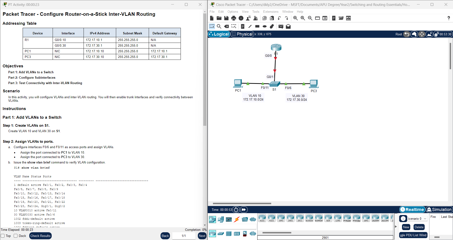
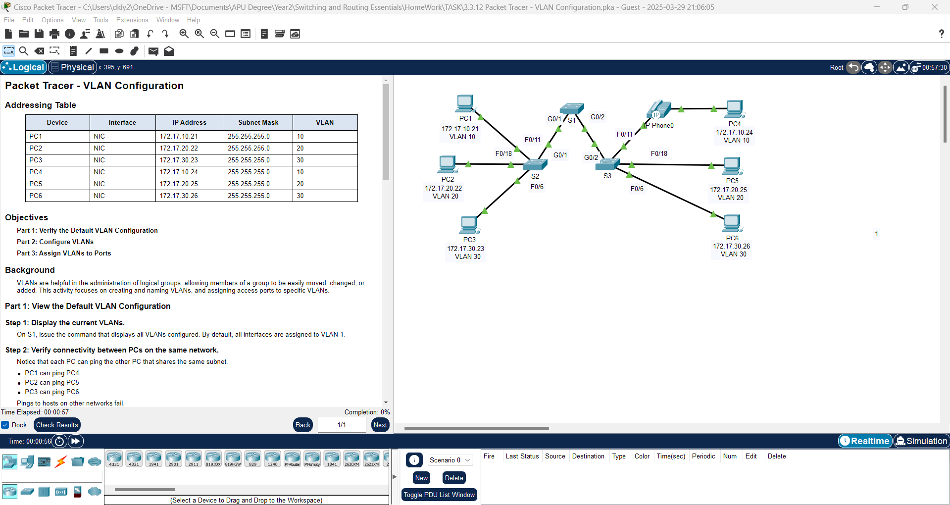
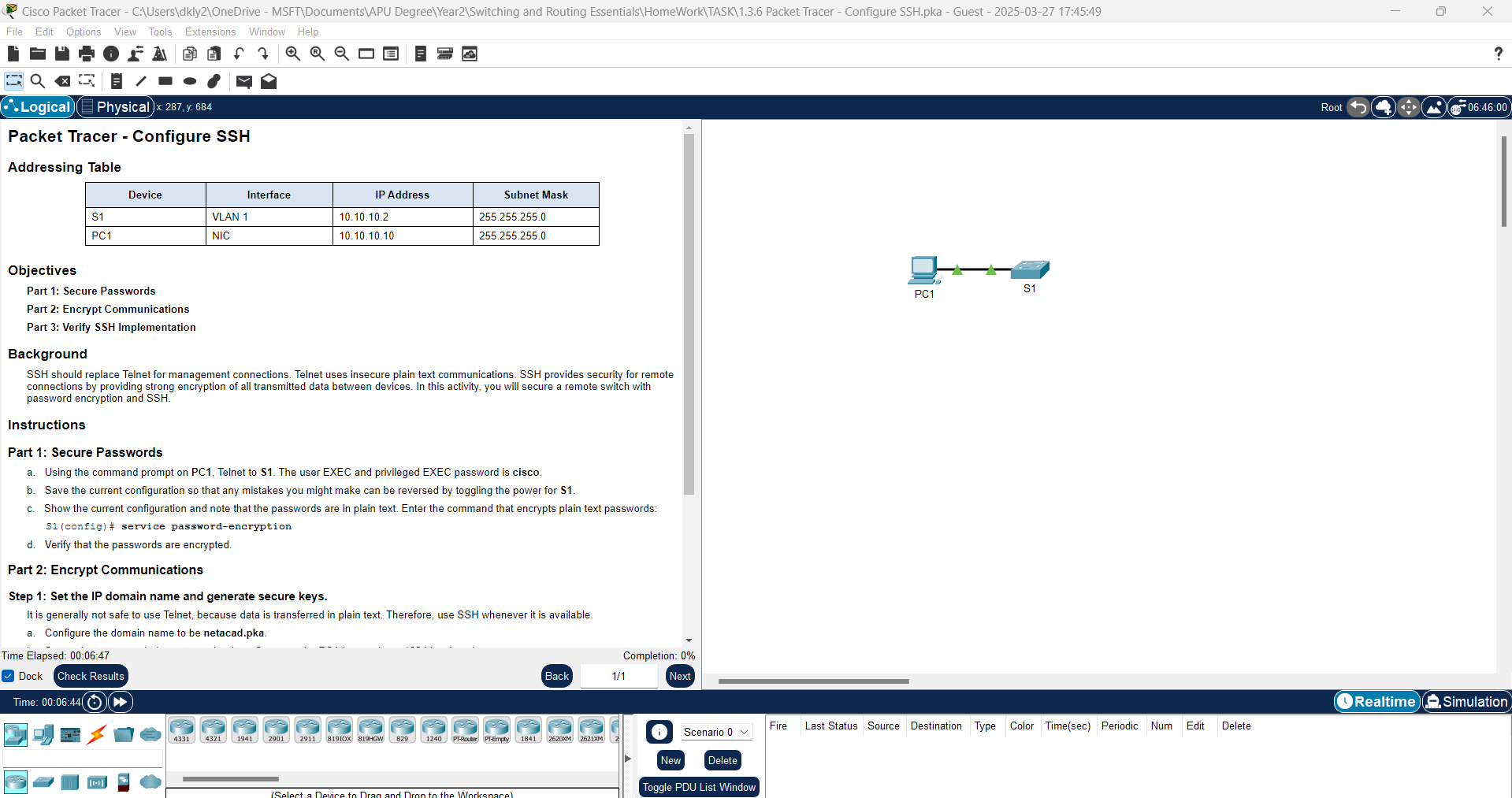
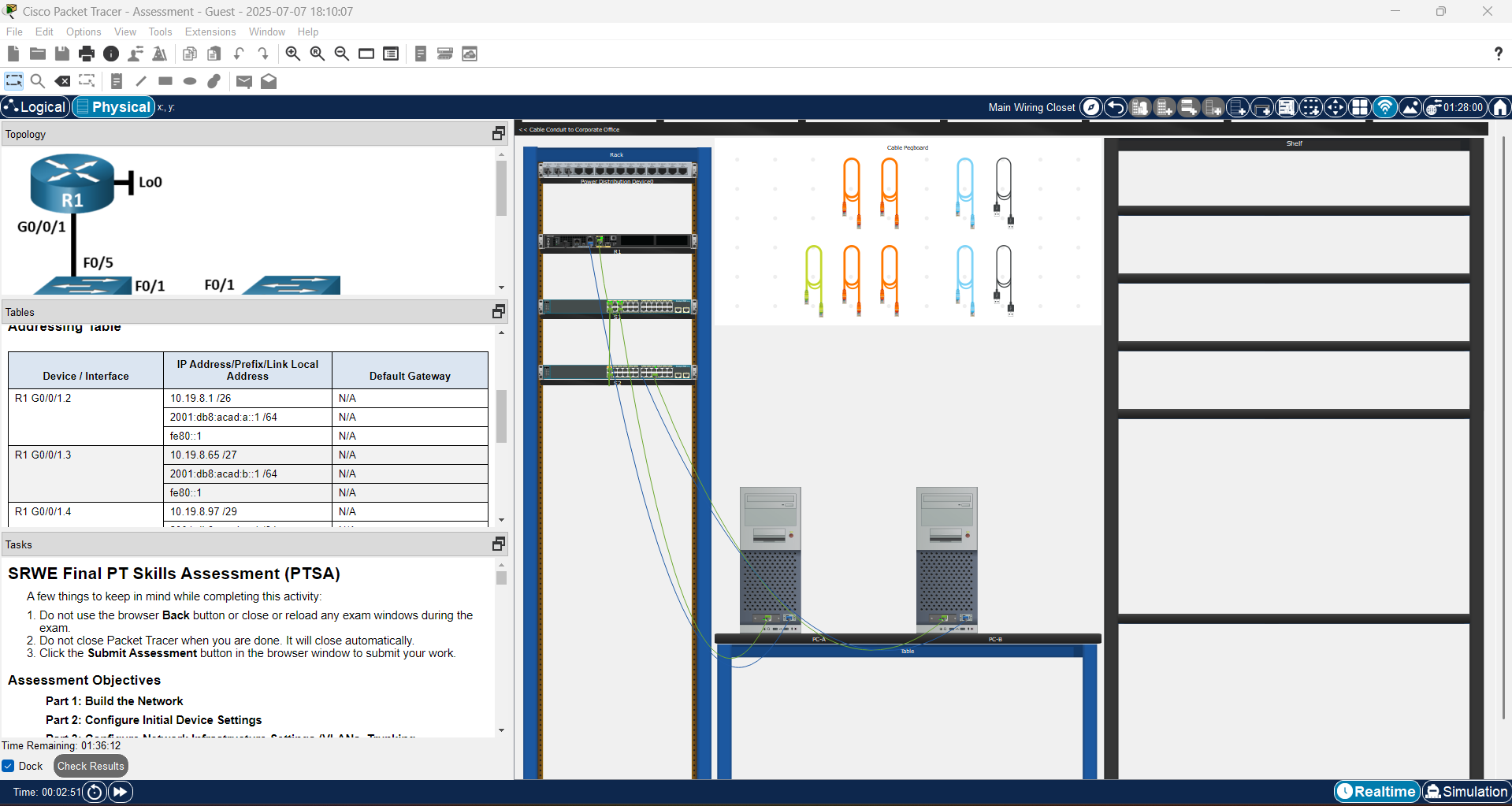
In this lab, we will configure Router-on-a-Stick for Inter-VLAN Routing using Packet Tracer. Router-on-a-Stick is a networking technique used to allow communication between devices in different VLANs. By utilizing a single physical interface on the router with subinterfaces, we can enable inter-VLAN communication without the need for multiple physical interfaces. In this exercise, you will learn how to configure VLANs, trunk ports, and subinterfaces on a router to establish communication between multiple VLANs.
| Device | Interface | IPv4 Address | Subnet Mask | Default Gateway
|
| R1 | G0/0.10 | 172.17.10.1 | 255.255.255.0 | N/A |
| R1 | G0/0.30 | 172.17.30.1 | 255.255.255.0 | N/A |
| PC1 | NIC | 172.17.10.10 | 255.255.255.0 | 172.17.10.1
|
| PC3 | NIC | 172.17.30.10 | 255.255.255.0 | 172.17.30.1 |
In this activity, you will configure VLANs and inter-VLAN routing. You will then enable trunk interfaces and verify connectivity between VLANs.
Instructions
Part 1: Add VLANs to a Switch
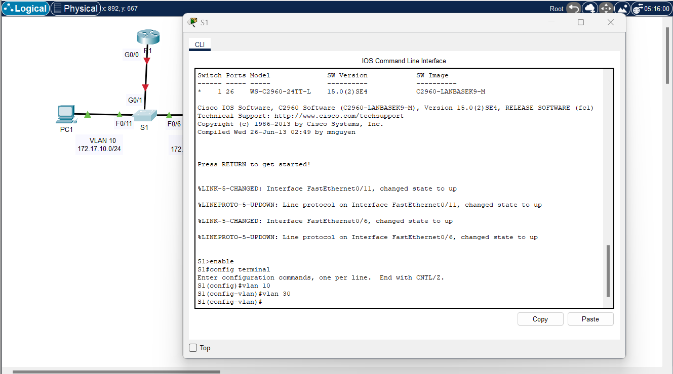
Step 1: Create VLANs on S1.
Create VLAN 10 and VLAN 30 on S1.
Solutions: Use
S1(config)#vlan 10
S1(config-vlan)#vlan 30 |
Step 2: Assign VLANs to ports.
a. Configure interfaces F0/6 and F0/11 as access ports and assign VLANs.
· Assign the port connected to PC1 to VLAN 10.
· Assign the port connected to PC3 to VLAN 30.
Solutions:
S1(config)#interface f0/11
S1(config-if)#switchport mode access
S1(config-if)#switchport access vlan 10
S1(config-if)#exit
S1(config)#interface f0/6
S1(config-if)#switchport mode access
S1(config-if)#switchport access vlan 30
S1(config-if)#exit |
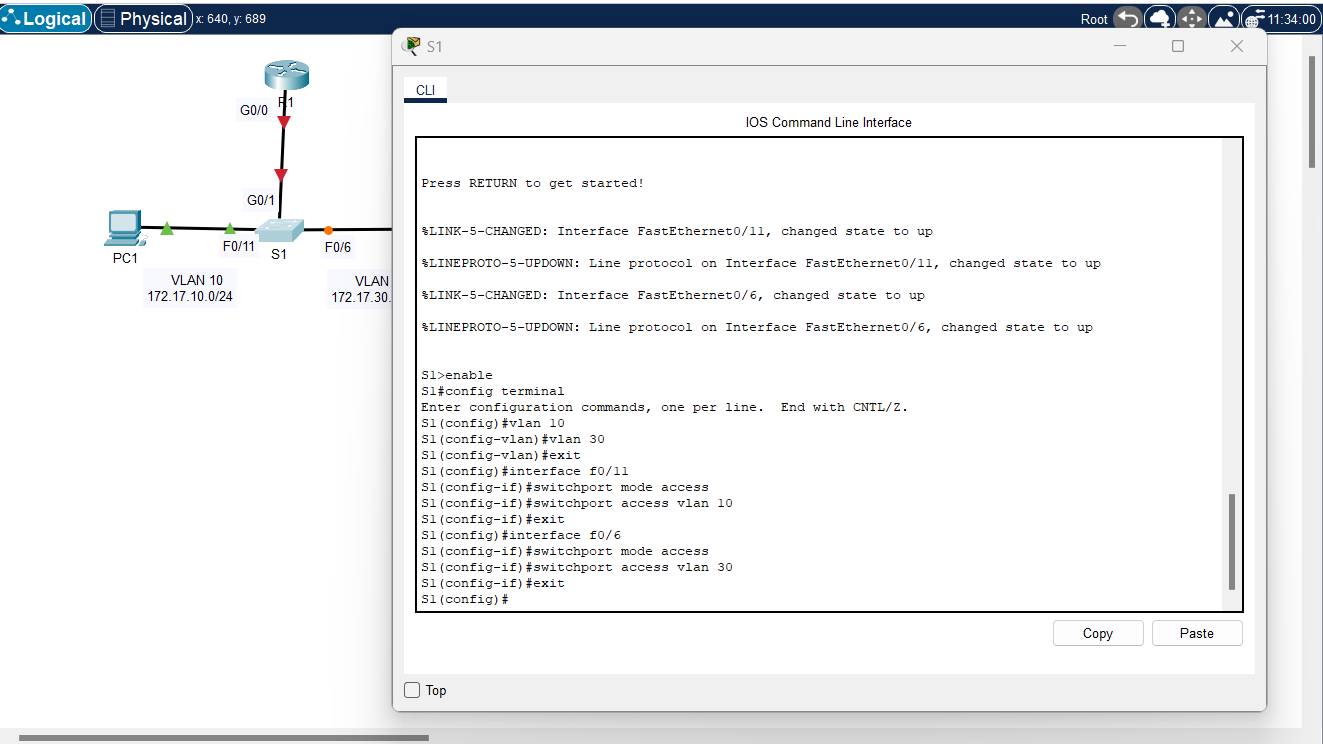
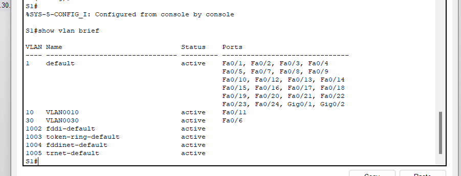
b. Issue the show vlan brief command to verify VLAN configuration.
Solutions:
Step 3: Test connectivity between PC1 and PC3.
From PC1, ping PC3.
Question:
Were the pings successful? Why did you get this result?
Answer: No, the pings between PC1 and PC3 is failed. Its because PC1 and PC3 are on different IP networks (PC1 and PC3 are on different VLANs and there is no inter-VLAN routing configured, they are effectively isolated from each other.)
Part 2: Configure Subinterfaces
Step 1: Configure subinterfaces on R1 using the 802.1Q encapsulation.
a. Create the subinterface G0/0.10.
· Set the encapsulation type to 802.1Q and assign VLAN 10 to the subinterface.
· Refer to the Address Table and assign the correct IP address to the subinterface.
Solutions:
R1(config)# int g0/0.10
R1(config-subif)# encapsulation dot1Q 10
R1(config-subif)# ip address 172.17.10.1 255.255.255.0 |
b. Repeat for the G0/0.30 subinterface.
Solutions:
R1(config)# int g0/0.30
R1(config-subif)# encapsulation dot1Q 30
R1(config-subif)# ip address 172.17.30.1 255.255.255.0 |
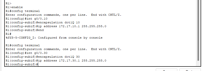
Step 2: Verify Configuration.
a. Use the show ip interface brief command to verify subinterface configuration. Both subinterfaces are down. Subinterfaces are virtual interfaces that are associated with a physical interface. Therefore, in order to enable subinterfaces, you must enable the physical interface that they are associated with.
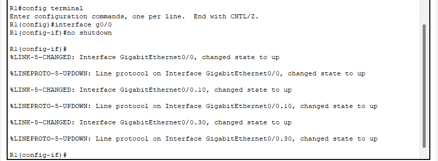
b. Enable the G0/0 interface. Verify that the subinterfaces are now active.
Solutions:
R1(config)#interface g0/0
R1(config-if)#no shutdown |
Part 3: Test Connectivity with Inter-VLAN Routing
Step 1: Ping between PC1 and PC3.
Question:
From PC1, ping PC3. The pings should still fail. Explain.
Answer: The switch has not yet been configured with a trunk port to connect to the router, preventing inter-VLAN communication.
Step 2: Enable trunking.
a. On S1, issue the show vlan command.
Question:
What VLAN is G0/1 assigned to?
Answer: VLAN 1
b. Because the router was configured with multiple subinterfaces assigned to different VLANs, the switch port connecting to the router must be configured as a trunk. Enable trunking on interface G0/1.
Solutions:
S1(config)#int g0/1
S1(config-if)#switchport mode trunk |

Question:
How can you determine that the interface is a trunk port using the show vlan command?
Answer: When you run the show vlan command, access ports are displayed under their assigned VLANs. However, if an interface is configured as a trunk port, it will no longer appear in the output because trunk ports are not limited to a single VLAN—they carry traffic for multiple VLANs. To verify if an interface is a trunk port, use:
c. Issue the show interface trunk command to verify that the interface is configured as a trunk.
Solutions:
Step 3: Test Connectivity
If the configurations are correct, PC1 and PC3 should be able to ping their default gateways and each other.
Question:
What addresses do PC1 and PC3 use as their default gateway addresses?
Answer:
- PC1 uses 172.17.10.1 as its default gateway.
- PC3 uses 172.17.30.1 as its default gateway.
These default gateway addresses correspond to the router's subinterfaces (G0/0.10 and G0/0.30), which handle inter-VLAN routing.
Upon successful completion of this exercise, you will have configured Router-on-a-Stick inter-VLAN routing and verified that devices in different VLANs can communicate with each other. This configuration is crucial for efficient network management and segmentation, ensuring that traffic between VLANs is routed appropriately. Mastery of this technique is an essential skill for network engineers, as it provides a scalable solution to manage communication between isolated networks.


