CCNA: Switching, Routing, and Wireless Essentials (Version 7.00) - SRWE Final PT Skills Assessment (PTSA)
14 mins
·
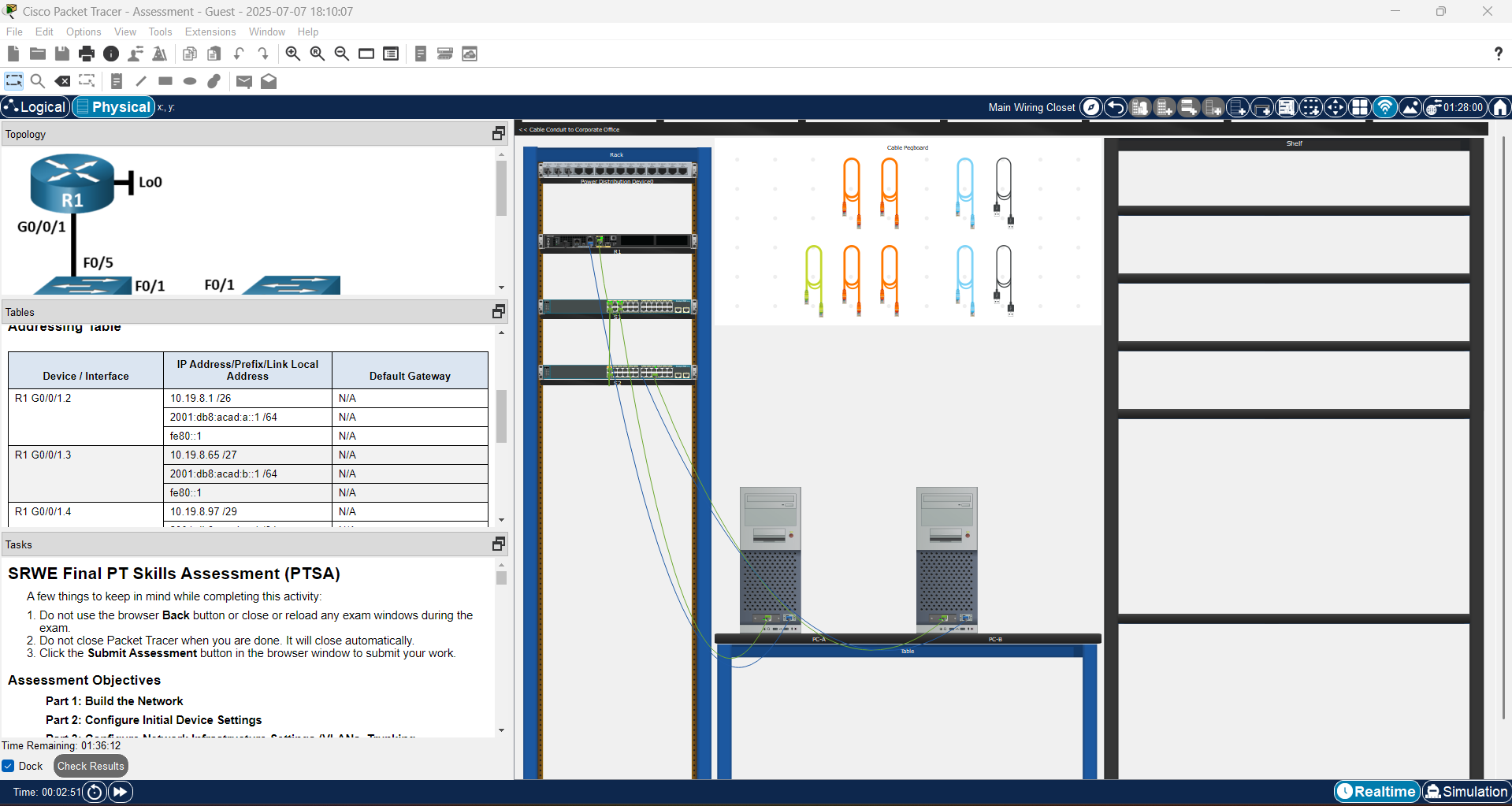
This practical assessment is designed to evaluate your hands-on skills and theoretical knowledge in configuring and troubleshooting a realistic network environment using Cisco Packet Tracer. Utilizing Physical Mode, this assessment simulates real-world scenarios, allowing you to virtually assemble, cable, and configure networking devices just as you would in a physical lab.
By completing this task, you will demonstrate your understanding of key concepts in switching, routing, VLANs, wireless configuration, and basic network security, as taught throughout the CCNA SRWE course.
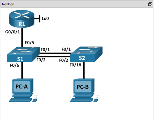
Topology
The Topology of CCNA: Switching, Routing, and Wireless Essentials V7
VLAN Table
VLAN
Router
Subinterface
VLAN
Name
2
G0/0/1.2
Bikes
3
G0/0/1.3
Trikes
4
G0/0/1.4
Management
5
N/A
Parking
6
G0/0/1.6
Native
Addressing Table
Device
/ Interface
IP
Address/Prefix/Link Local Address
Default
Gateway
R1
G0/0/1.2
10.19.8.1
/26
N/A
R1 G0/0/1.2
2001:db8:acad:a::1
/64
N/A
R1
G0/0/1.
fe80::1
N/A
R1
G0/0/1.3
10.19.8.65
/27
N/A
R1
G0/0/1.3
2001:db8:acad:b::1
/64
N/A
R1
G0/0/1.3
fe80::1
N/A
R1
G0/0/1.4
10.19.8.97
/29
N/A
R1
G0/0/1.4
2001:db8:acad:c::1
/64
N/A
fe80::1
N/A
R1 G0/0/1.6
N/A
N/A
R1
Loopback0
209.165.201.1
/27
N/A
R1
Loopback0
2001:db8:acad:209::1
/64
N/A
R1
Loopback0
fe80::1
N/A
S1 VLAN
4 SVI
10.19.8.98
/29
10.19.8.97
S2 VLAN
4 SVI
10.19.8.99
/29
10.19.8.97
PC-A
NIC
DHCP
for IPv4 address
DHCP
for IPv4 default gateway
PC-A
NIC
2001:db8:acad:a::50
/64
fe80::1
PC-B
NIC
DHCP
for IPv4 address
DHCP
for IPv4 default gateway
PC-B NIC
2001:db8:acad:b::50
/64
fe80::1
Note: There is no interface on the router that
supports VLAN 5.
Task: SRWE Final PT Skills Assessment (PTSA)
A few things to keep in mind while completing this activity:
1.Do not use the browser Back button or close or reload any exam windows during the exam.
2.Do not close Packet Tracer when you are done. It will close automatically.
3.Click the Submit Assessment button in the browser window to submit your work.
Assessment Objectives
Part 1: Build the Network
Part 2: Configure Initial Device Settings
Part 3: Configure Network Infrastructure Settings (VLANs, Trunking, EtherChannel)
Part 4: Configure Host Support
Introduction
In this Packet Tracer Skills Assessment (PTSA) you will configure the devices in a small network. You must configure a router, two switches, and two PCs to support both IPv4 and IPv6 connectivity. Your router and switches must also be managed securely. You will configure inter-VLAN routing, DHCP, Etherchannel, and port-security.
All of your tasks will be performed in PT Physical Mode. You will not be able to access the logical topology for this assessment. Network devices must be configured from a direct console connection.
Instructions
Part 1: Build the Network
a. Move the required devices into the equipment rack.
b. Place the PCs on the table.
c. Connect the devices according to the topology diagram.
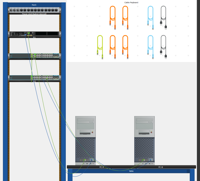
Answer: Place the Router (R1), Switches (S1 & S2) on the RACK. Place the PC1 & PC2 on the Table. Then, use a Copper Straight-Through cable on the Cable Pegboard to connect all devices according to the topology. Turn on the Router, Switches & All PCs. (You may refer to the attached image below.)
Build the Network - SRWE Final PT Skills Assessment (PTSA)
Part 2: Configure Initial Device Settings
All IOS device configuration must be made through direct console connections.
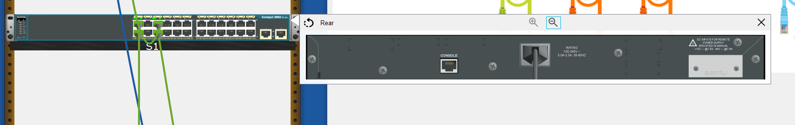
Answer: Right on click Switch –> Inspect Rear –> Console port. Then, use the Console Cable and plug into the Console Port. After that connect to the PC-A R232 Port as shown.
Show Console port on Switch
Step 1: Configure R1 Basic Settings and Device Hardening
a. Configure basic settings.
1) Prevent the router from attempting to resolve incorrectly entered commands as domain names.
2) Configure the R1 hostname.
3) Configure an appropriate MOTD banner.
Answer:
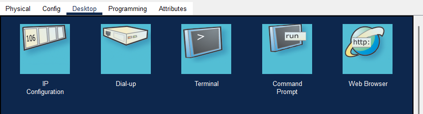
PKA PC & Laptop Desktop Programs
On the PC-A (PC1) > Desktop > Terminal. Then, Config the commands bellow:
Router#config t
Router(config)#no ip domain lookup
Router(config)#hostname R1
R1(config)#banner motd #Unauthorized Acess is Prohibited#
b. Configure password security.
1) Configure the console password and enable connections.
2) Configure an enable secret password.
3) Encrypt all clear text passwords.
4) Set the minimum length of newly created passwords to 10 characters.
Answer:
R1#config t
R1(config)#line console 0
R1(config-line)#password ciscopassword
R1(config-line)#login
R1(config-line)#exit
R1(config)#enable secret ciscopassword
R1(config)#service password-encryption
R1(config)#security passwords min-length 10
c. Configure SSH.
1) Create an administrative user in the local user database.
= Username: admin
= Encrypted Password: admin1pass
2) Configure the domain name as ccna-ptsa.com
3) Create an RSA crypto key with a modulus of 1024 bits.
4) Ensure that more secure version of SSH will be used.
5) Configure the vty lines to authenticate logins against the local user database.
6) Configure the vty lines to only accept connections over SSH.
Answer:
R1(config)#username admin secret admin1pass
R1(config)#ip domain name ccna-ptsa.com
R1(config)#crypto key generate rsa 1024
R1(config)#ip ssh version 2
R1(config)#line vty 0 15
R1(config-line)#login local
R1(config-line)#transport input ssh
R1(config-line)#exit
Step 2: Configure router interfaces.
a. Configure R1 with a loopback interface. Configure the loopback0 with IPv4 and IPv6 addressing according to the addressing table.
b. Configure Router Subinterfaces
1) Prepare the router to be configured with IPv6 addresses on its interfaces.
2) Use the information in the Addressing Table and VLAN Table to configure subinterfaces on R1:
= Interfaces should be configured with IPv4 and IPv6 addressing.
= All addressed interfaces should use fe80::1 as the link local address.
= Use the VLAN table to assign VLAN membership to the subinterfaces.
3) Be sure to configure the native VLAN interface.
a. Configure the host computers to use DHCP for IPv4 addressing.
b. Statically assign the IPv6 GUA and default gateway addresses using the values in the Addressing Table.
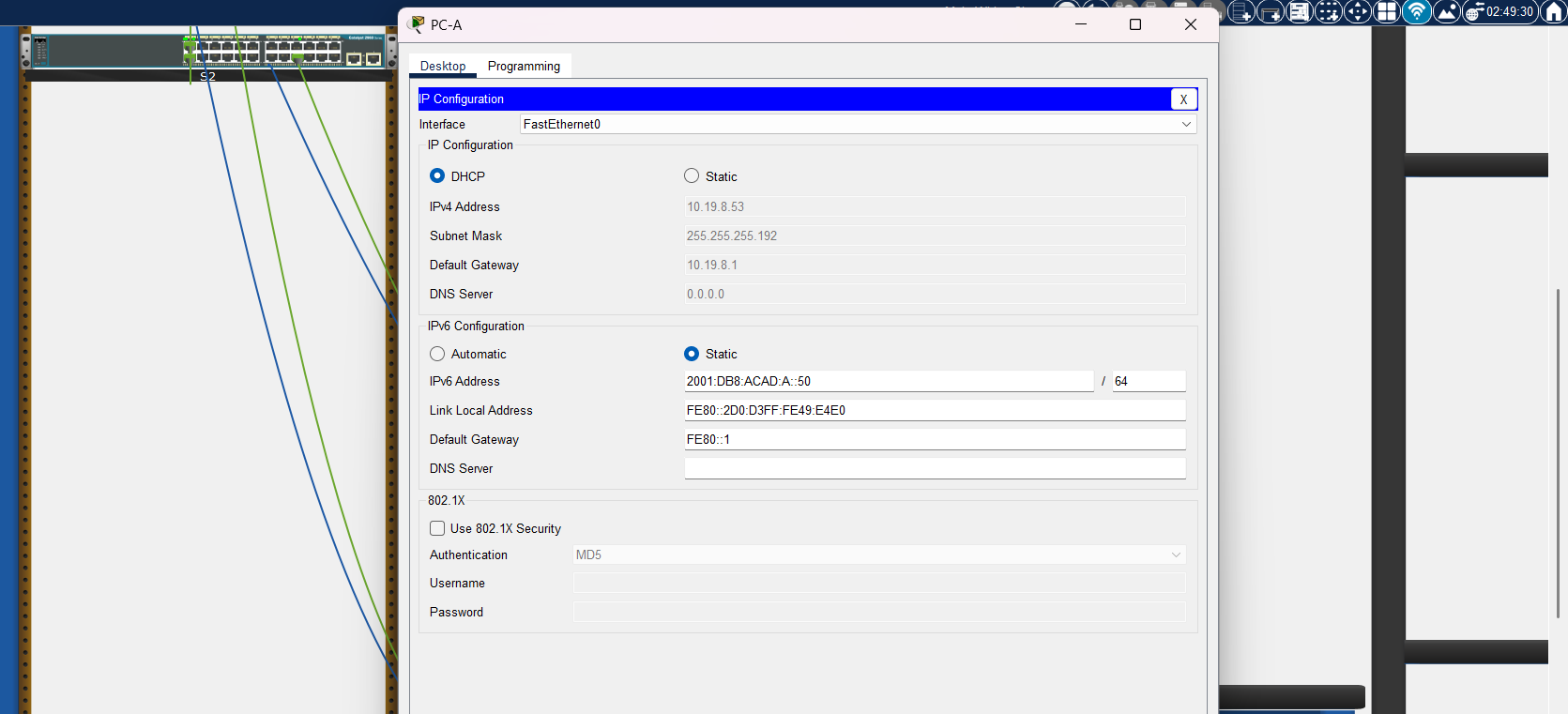
Answer: Open the IP Configuration on PC-A (PC1) & PC-B (PC2).
Cisco Packet Tracer PC Desktop Program
PC-A (PC1): On PC-A, set the IP Configuration IPv4 to DHCP. IPv6 Configuration as Static and fill in the 2001:db8:acad:a::50 /64 and the Default Gateway for IPv6 Configuration as fe80::1.
Configure the IP Configurations of PC-A on PKA
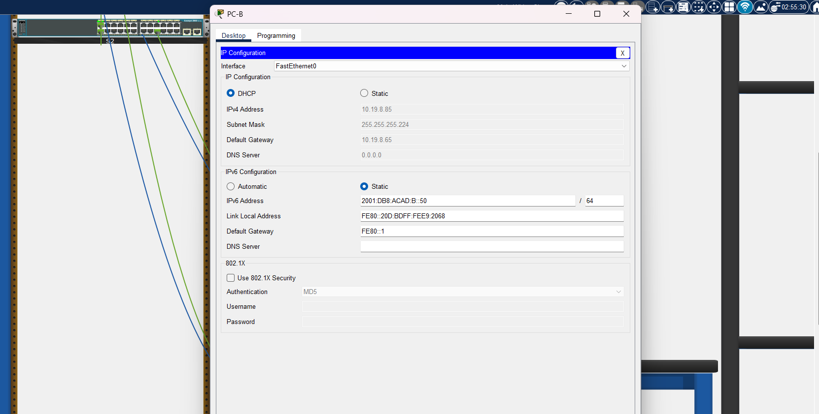
PC-B (PC2): On PC-B, set the IP Configuration IPv4 to DHCP. IPv6 Configuration as Static and fill in the 2001:db8:acad:a::50 /64 and the Default Gateway for IPv6 Configuration as fe80::1.
Configure the IP Configurations of PC-B on PKA
The CCNA: Switching, Routing, and Wireless Essentials (SRWE) Final Packet Tracer Skills Assessment (PTSA) provides a comprehensive opportunity to apply and reinforce the skills acquired throughout the course. By working in Cisco Packet Tracer’s Physical Mode, students are challenged to simulate real-world networking environments—assembling, configuring, and troubleshooting devices in a hands-on, practical context.
Successfully completing the assessment demonstrates a solid grasp of critical networking concepts, including VLAN implementation, routing configuration, wireless setup, and foundational network security. More importantly, it equips students with the confidence and practical experience necessary for real-world networking scenarios and prepares them for further certifications and professional opportunities in the field of networking.
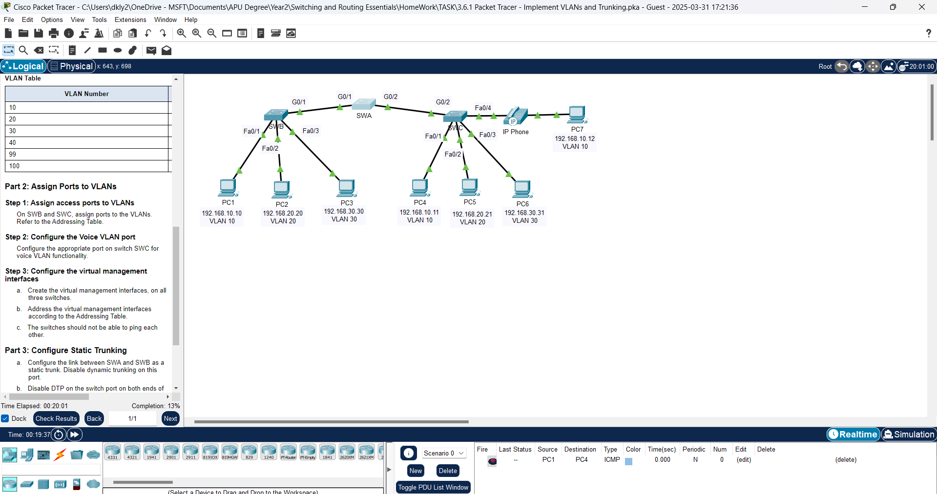
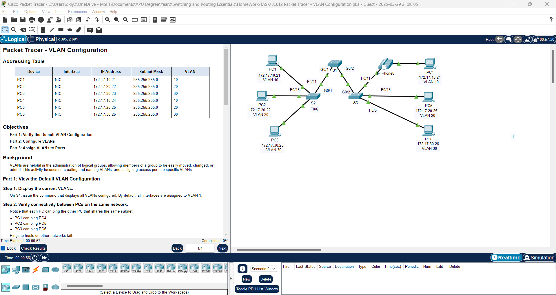
Learn how to implement VLANs and trunking in Packet Tracer. Follow step-by-step instructions to configure VLANs, assign ports, and establish trunk connections.
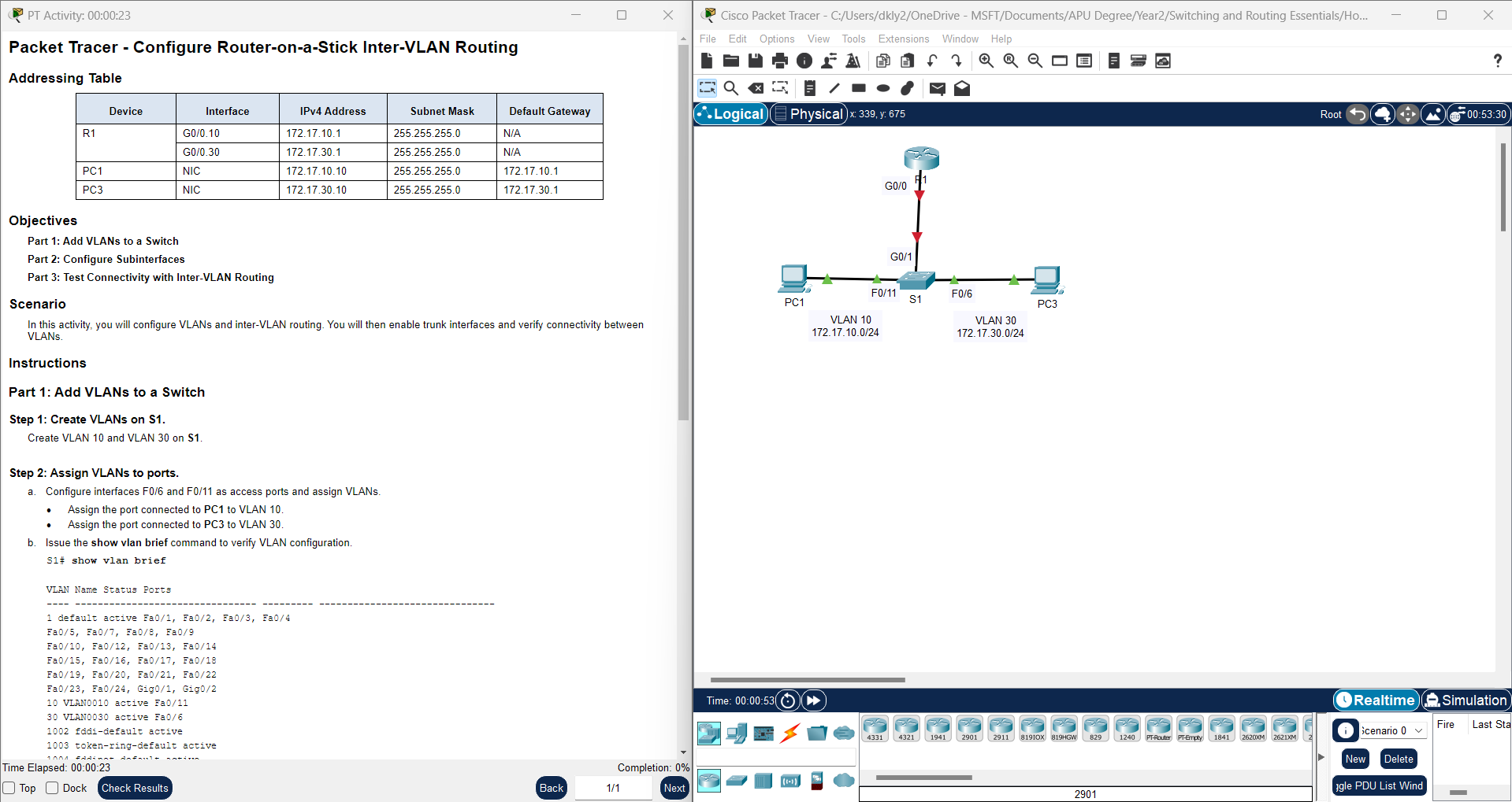
Learn how to configure Router-on-a-Stick inter-VLAN routing in Packet Tracer. This guide covers VLAN setup, trunk port configuration, and inter-VLAN communication.
Step-by-step guide to configuring trunk ports in Cisco Packet Tracer. Learn how to set up VLAN trunks, verify trunk status, and troubleshoot connectivity issues.
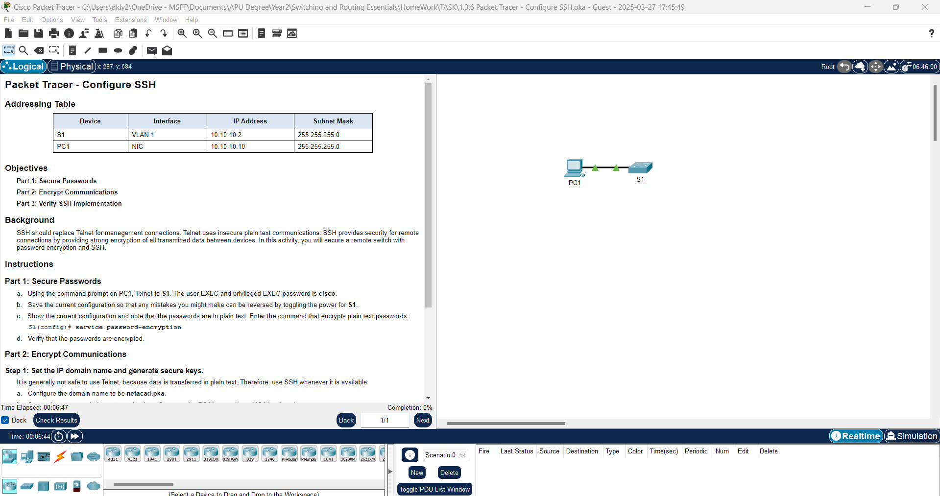
1.3.6 Packet Tracer - SSH Configuration | Secure Remote Access on a Cisco Switch
Step-by-step guide on configuring SSH on a Cisco switch using Packet Tracer. Learn how to enable SSH, set up user authentication, and enhance network security.
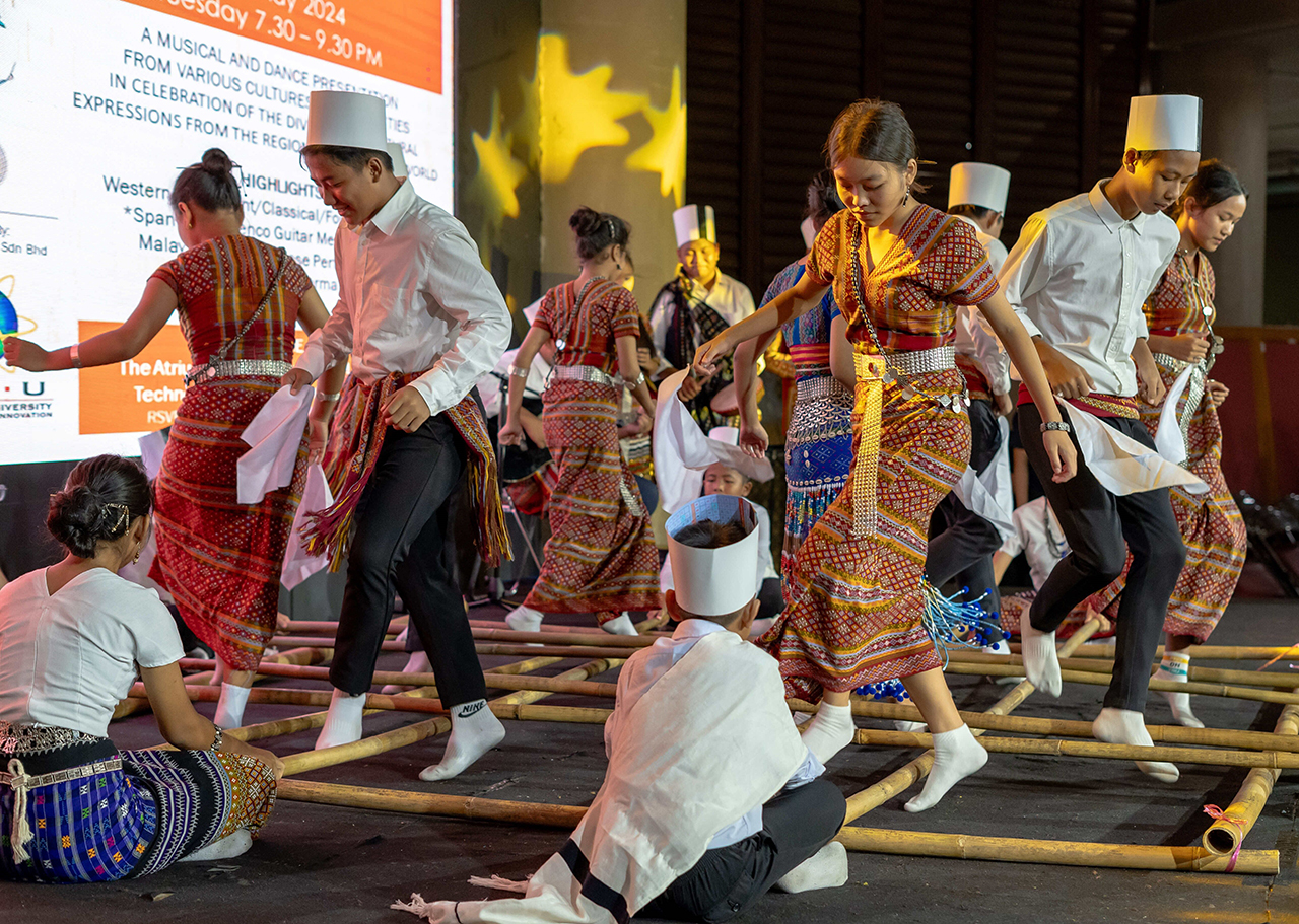
A Day of Global Harmony at APU: World Cultural Diversity Day
Experience the vibrant celebration of World Cultural Diversity Day at Asia Pacific University of Technology & Innovation, where Sustainable Future Fusion (SFF) united global cultures to inspire sustainable innovation and unity.