In this activity, you will learn how to configure and verify trunk ports on Cisco switches using Packet Tracer. Trunking allows multiple VLANs to communicate across switches by forwarding tagged traffic, ensuring efficient network segmentation. You will also set the native VLAN and troubleshoot potential trunking issues.
BackgroundTrunks are required to pass VLAN information between switches. A port on a switch is either an access port or a trunk port. Access ports carry traffic from a specific VLAN assigned to the port. A trunk port by default is a member of all VLANs. Therefore, it carries traffic for all VLANs. This activity focuses on creating trunk ports and assigning them to a native VLAN other than the default.
Instructions
Part 1: Verify VLANs
Step 1: Display the current VLANs.
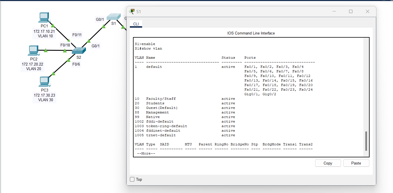
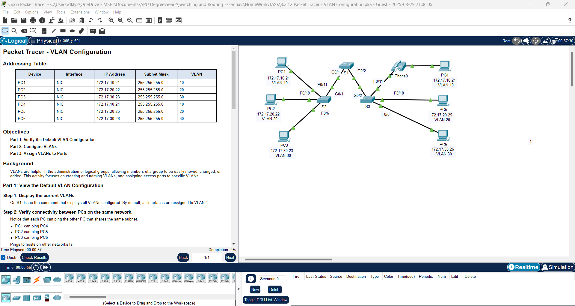
a. On S1, issue the command that will display all VLANs configured. There should be ten VLANs in total. Notice that all 26 access ports on the switch are assigned to VLAN 1.
Solutions: Use "show vlan" or "show vlan brief" command on Switch 1 (S1).
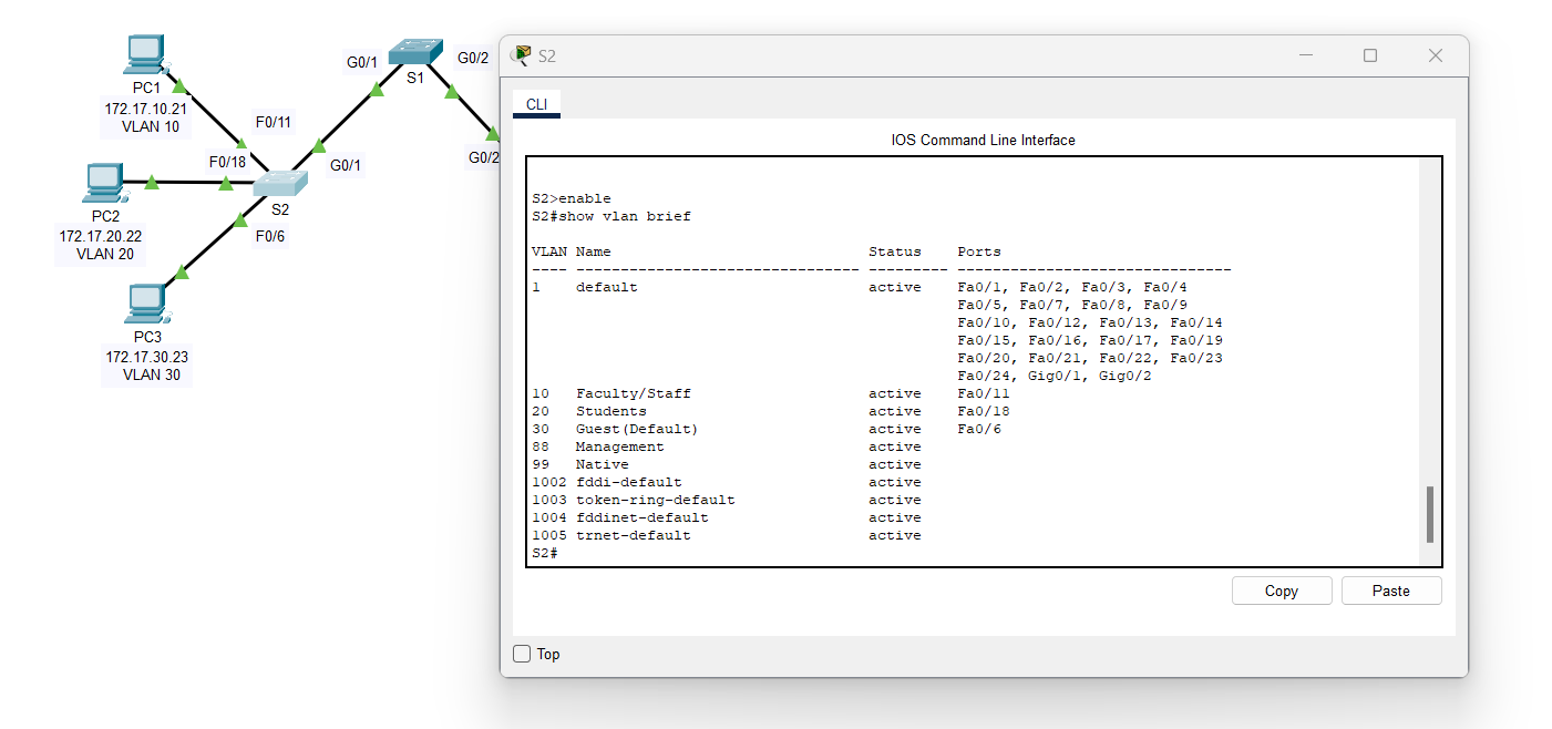
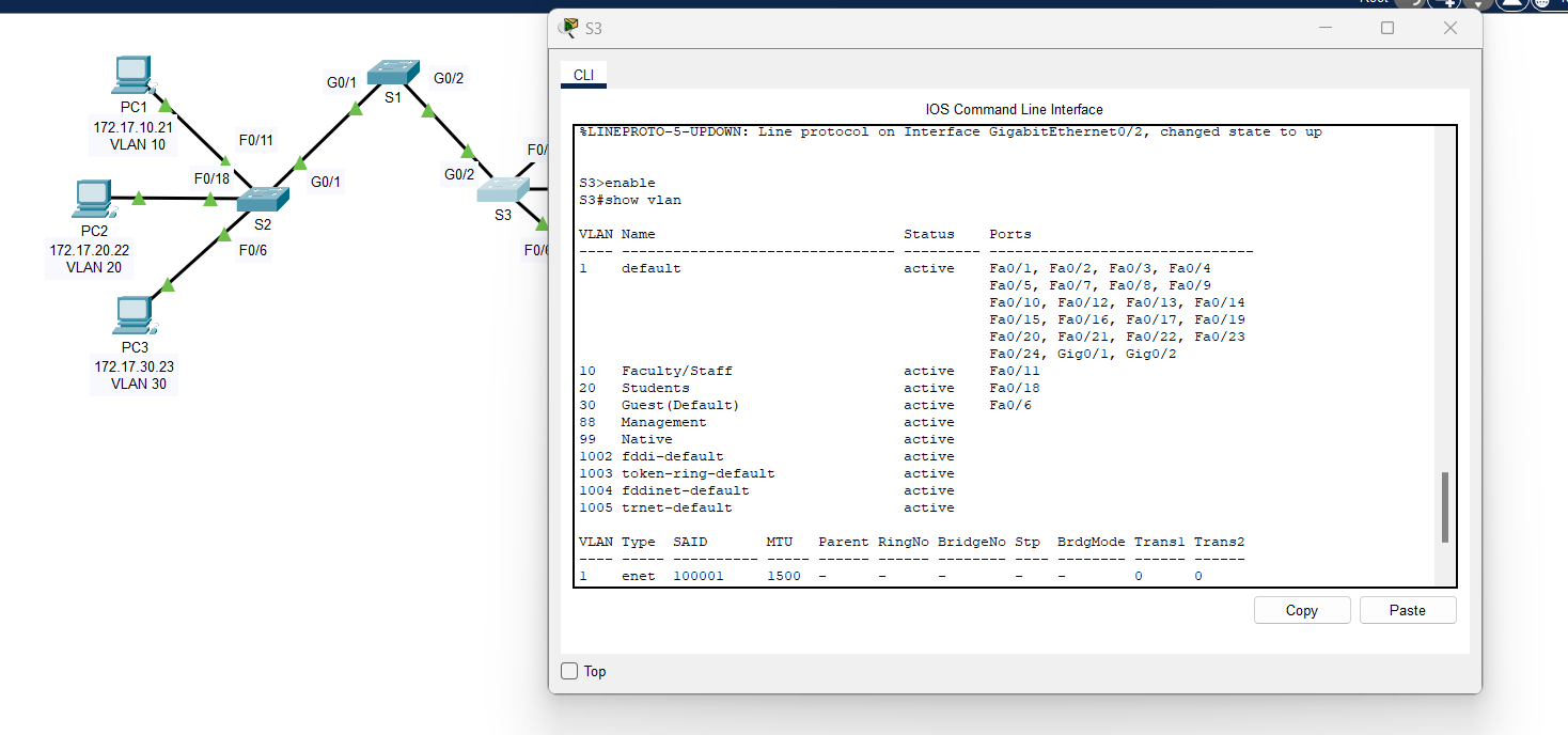
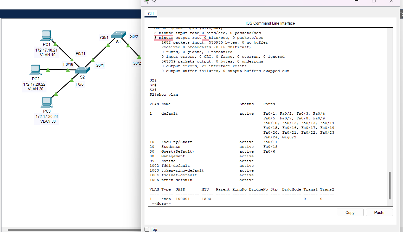
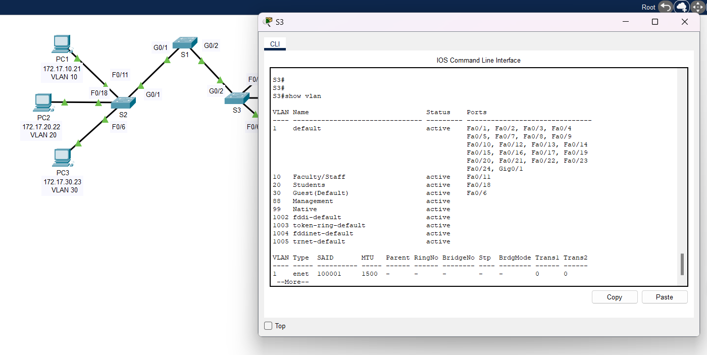
b. On S2 and S3, display and verify that all the VLANs are configured and assigned to the correct switch ports according to the Addressing Table.
Solutions:
1. Switch 2 (S2):
2. Switch 3 (S3):
Step 2: Verify loss of connectivity between PCs on the same network.
Ping between hosts on the same the VLAN on the different switches. Although PC1 and PC4 are on the same network, they cannot ping one another. This is because the ports connecting the switches are assigned to VLAN 1 by default. In order to provide connectivity between the PCs on the same network and VLAN, trunks must be configured.
Part 2: Configure Trunks
Step 1: Configure trunking on S1 and use VLAN 99 as the native VLAN.
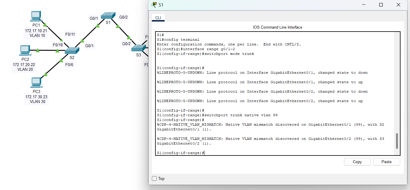
a. Configure G0/1 and G0/2 interfaces on S1 for trunking.
Solutions:
S1(config)# interface range g0/1 - 2
S1(config-if)# switchport mode trunk
|
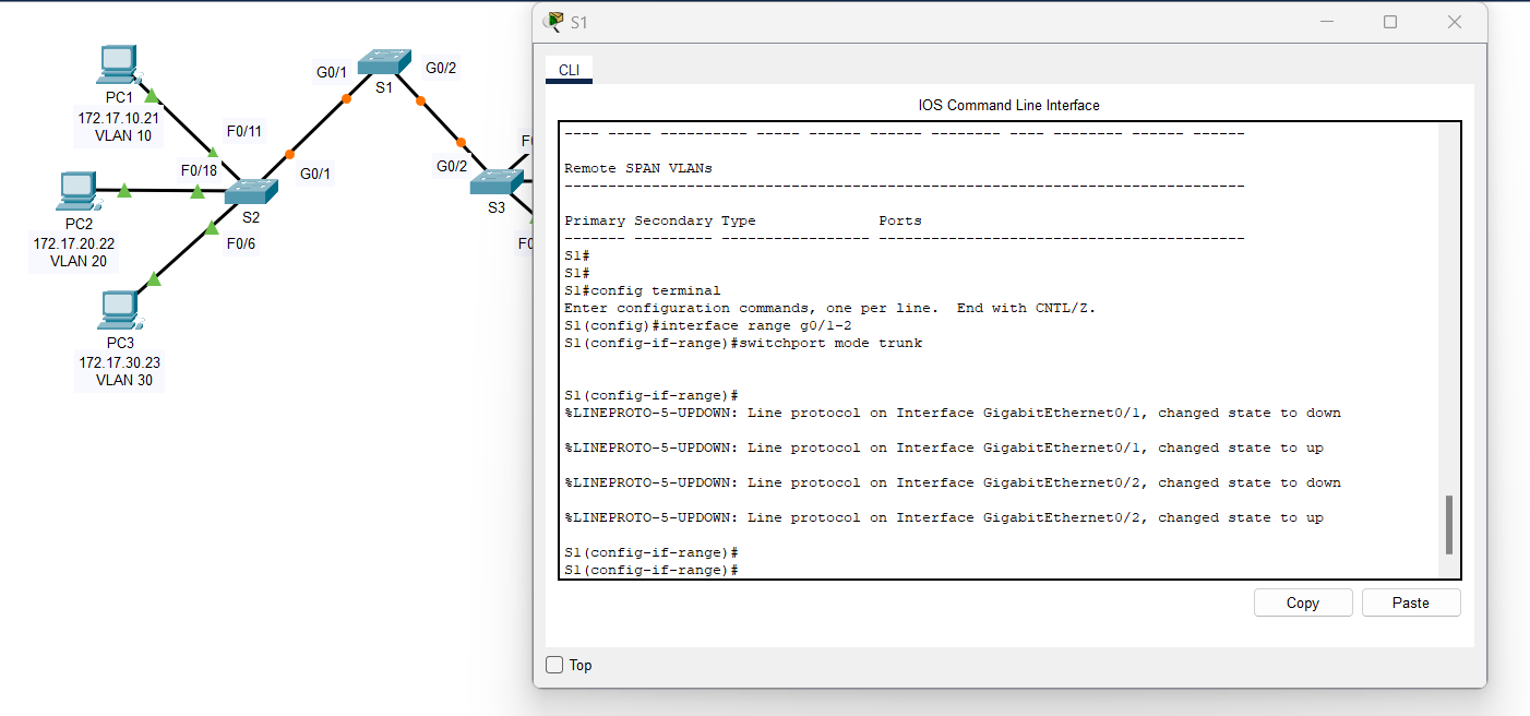
b. Configure VLAN 99 as the native VLAN for G0/1 and G0/2 interfaces on S1.
Solutions:
S1(config-if)# switchport trunk native vlan 99
|
Notes: The trunk port takes about a short time to become active due to Spanning Tree Protocol. Click Fast Forward Time to speed the process. After the ports become active, you will periodically receive the following syslog messages:
%CDP-4-NATIVE_VLAN_MISMATCH: Native VLAN mismatch discovered on GigabitEthernet0/2 (99), with S3 GigabitEthernet0/2 (1).
%CDP-4-NATIVE_VLAN_MISMATCH: Native VLAN mismatch discovered on GigabitEthernet0/1 (99), with S2 GigabitEthernet0/1 (1). |
You configured VLAN 99 as the native VLAN on S1. However, S2 and S3 are using VLAN 1 as the default native VLAN as indicated by the syslog message.
Question:
Although you have a native VLAN mismatch, pings between PCs on the same VLAN are now successful. Explain.
Answer: Based on this scenario, a native VLAN mismatch, but despite this mismatch, pings between PCs on the same VLAN are still successful. Let's break it down:
1) Understanding the Native VLAN Mismatch
- S1 is configured with VLAN 99 as the native VLAN.
- S2 and S3 are using VLAN 1 as the native VLAN.
- Syslog messages warn about the mismatch, but connectivity remains.
Normally, a native VLAN mismatch could cause traffic issues because:
- Frames sent on the native VLAN (untagged) might not be interpreted correctly by the receiving switch.
- This can lead to misdirected traffic or security vulnerabilities.
2) Why Are Pings Still Successful?
The key reason pings are still working is Dynamic Trunking Protocol (DTP). Here's what happened:
- DTP automatically negotiated trunking on the connected ports.
- When trunking is enabled, frames for all VLANs (except the native VLAN) are tagged.
- This means frames for VLANs used by the PCs (e.g., VLAN 10, VLAN 20) remain tagged and unaffected by the native VLAN mismatch.
- Only native VLAN frames are affected by the mismatch.
PCs communicate on specific VLANs (not the native VLAN).
Since these VLANs are trunked with tagged frames, the mismatch does not impact them.
- Native VLAN mismatch affects untagged traffic only.
- If VLAN 99 traffic (untagged from S1) reaches S2/S3 (expecting VLAN 1), it could be misinterpreted.
- However, since user VLANs (e.g., VLAN 10, VLAN 20) are tagged, their traffic flows normally.
3) What Would Be the Real Impact of the Mismatch?
- Control plane protocols like CDP, VTP, and DTP (which use the native VLAN) might not work properly.
- If any hosts or management interfaces rely on the native VLAN, they may experience connectivity issues.
- If an attacker exploits the mismatch, they could potentially inject packets into another VLAN (VLAN hopping attack).
Pings are successful because DTP has ensured that trunking is properly established, and VLAN-tagged traffic is unaffected by the native VLAN mismatch. However, it's still a best practice to correct the mismatch to avoid potential issues.
Step 2: Verify trunking is enabled on S2 and S3.
On S2 and S3, issue the show interface trunk command to confirm that DTP has successfully negotiated trunking with S1 on S2 and S3. The output also displays information about the trunk interfaces on S2 and S3. You will learn more about DTP later in the course.
Question:
Which active VLANs are allowed to cross the trunk?
Answer: VLANs 1,10,20,30,88,99
Step 3: Correct the native VLAN mismatch on S2 and S3.
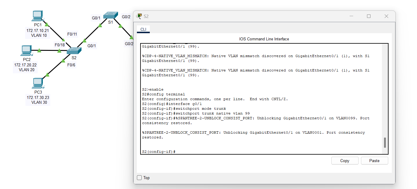
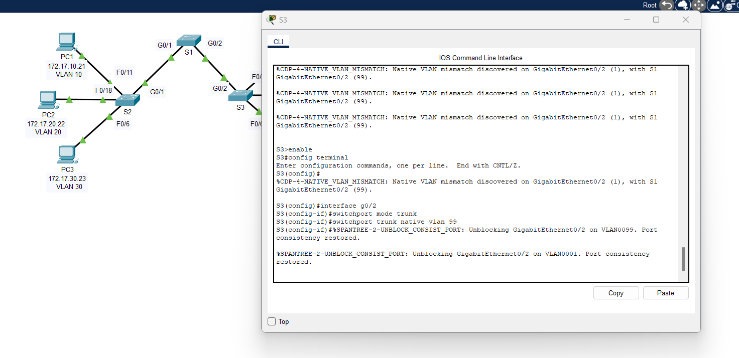
a. Configure VLAN 99 as the native VLAN for the appropriate interfaces on S2 and S3.
Solutions:
1. Switch 2 (S2):
S2(config)#interface g0/1
S2(config-if)#switchport mode trunk
S2(config-if)#switchport trunk native vlan 99 |
2. Switch 3 (S3):
S3(config)#interface g0/2
S3(config-if)#switchport mode trunk
S3(config-if)#switchport trunk native vlan 99 |
b. Issue show interface trunk command to verify the correct native VLAN configuration.
Step 4: Verify configurations on S2 and S3.
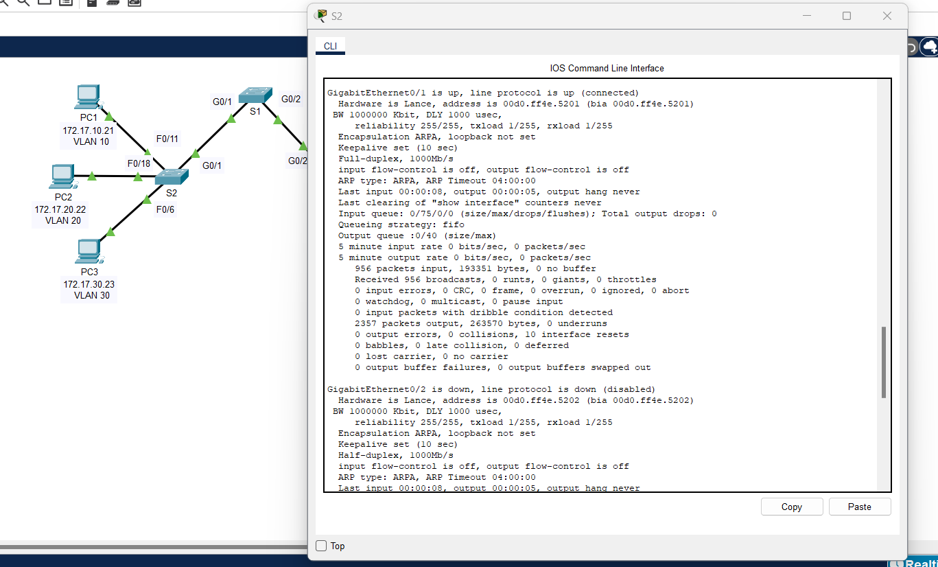
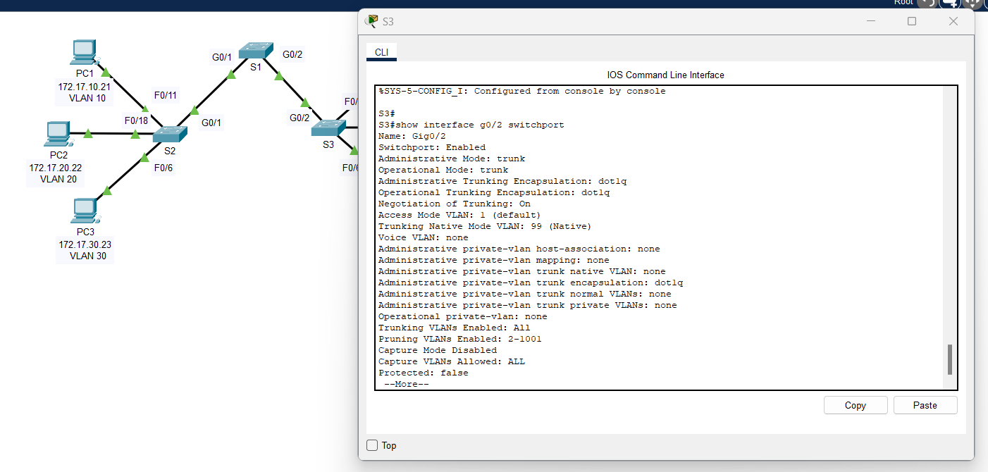
a. Issue the show interface interface switchport command to verify that the native VLAN is now 99.
Solutions: You can use the "show interface [port] switchport" or "show interface" command on the terminal.
1) Switch 2 (S2):
2) Switch 3 (S3):
b. Use the show vlan command to display information regarding configured VLANs.
Solutions: Use "show vlan" on the terminal.
1) Switch 2 (S2):
2) Switch 3 (S3):
Question:
Why is port G0/1 on S2 no longer assigned to VLAN 1?
Answer: Port G0/1 on S2 is no longer assigned to VLAN 1 because it has been configured as a trunk port, and trunk ports are not shown in VLAN assignment tables. Instead, they carry multiple VLANs and can be checked using "show interfaces trunk".
By successfully configuring trunk ports, you enable seamless VLAN communication between switches, improving network efficiency and scalability. Understanding VLAN trunking is essential for network administrators to maintain proper traffic flow, prevent misconfigurations, and ensure a well-structured network infrastructure.
